We need properties in order to calculate the energy changes in engines and process plant - ultimately this influences fuel demand and efficiency. Engineers should be familiar with the properties of ideal gases, and be able to use tables/ charts or computer programmes to get the properties of steam and refrigerants.
A property defines an equilibrium state and is independent of the path taken to reach that state.
From the state postulate , two independent properties determine the equilibrium state of a simple system - namely a collection of fluid molecules - and thereby determine all other properties. At equilibrium all "driving forces" acting on a system are balanced. The system is at the same temperature as its environment and any forces exerted by the system are counteracted by the surroundings. Some properties, for example temperature, relate strongly to the energy of the system - its potential to do work.
It is possible to combine two or more independent properties to form other properties, for example density,
$$ \rho = \frac{m}{V} $$
Or the reciprocal of density is termed "specific volume",
$$ v = \frac{V}{m} = \frac{1}{\rho} $$
A property has no dependence on path. By means of analogy consider altitude. A walker, reaching a particular map co-ordinate, will always achieve the same altitude regardless of the path taken. Intensive properties (T, p, v etc) show no dependence on the size of a system whereas extensive properties (V, m) do. The intensive properties of particular interest to us are temperature T, pressure p, specific volume v . Also, three terms will be described later: specific internal energy u, specific enthalpy h and specific entropy s. A special form of intensive property is the specific property - the quantity per unit mass (see specific volume above). The property might refer to liquid phase, gaseous phase, or some combination of the two.
The condition of a fluid is mapped against pressure and temperature on a phase diagram . The curves define equilibrium between gas-and-liquid, liquid-and-solid, and solid-and-gas. For example, along the curve from the triple point (T) to the critical point (C) liquid and gas are in equilibrium; two phases co-exist.
Figure 1 Phase diagram. T indicates the triple point and C indicates the critical point. A detailed plot for CO2 is available at the Engineering Toolbox site. (You will have to scroll down to see the graph.)
In the first half of these notes the focus is on ideal gases with the properties of dry air. Perfect gases follow simple behaviour, captured by the Ideal Gas Law.
In the second half of these notes the focus is on non-ideal gases, and mainly steam. The complex relationship between properties must be found from tables, charts or computer codes. Interactive charts on this website also allow such properties to be estimated.
2.) Ideal (or Perfect) Gas Law
In the Ideal Gas Law simple relationships apply to pressure, volume and temperature.
Most readers will be familiar with the laws of Charles, Boyle and Gay-Lussac. These can be combined as the Ideal Gas Law
where the specific gas constant R holds different values for different gases; its units are \(KJ kg^{-1} K^{-1} \). Note that V refers to volume whereas v refers to specific volume, that is volume per unit mass. The above equations differ a little from the versions used for Chemistry courses, which refer to substance (in kmol) rather than mass. R follows from the universal gas constant , \( \widetilde{R} \) , and molar mass
\begin{equation} R = \frac{\widetilde{R}}{\widetilde{m}} \end{equation}
where \( \widetilde{R}= 8.314 kJ \, kmol^{-1} \, K^{-1} \) for all ideal gases. A kilomole is the engineering unit of substance, namely \(6.022 \times 10^{26}\) molecules. The molar mass is the mass of 1 kmole (or 1 gram mole in the SI system). Approximate molar masses are tabulated below.
Table 1. Example molar masses
Substance
Air
Steam
Nitrogen
Oxygen
Argon
Chemical formula
-
\(H_2O\)
\(N_2\)
\(O_2\)
Ar
molar mass (in kg per kmol)
29
18
28
32
40
So the Ideal Gas Law could be expressed as,
\begin{equation} p V = n \widetilde{R} T \end{equation}
where \(n = m/\widetilde{m} \) is the amount of substance (in kmol).
The ideal gas law combines Charles's Law ( \(V \propto T)\) ), Boyles Law ( \(p \propto 1/V \)), and the Gay Lussac Law (\(p \propto T\)).
Example 2.010. A pressure vessel is intended to hold 5 kg of air at a temperature of 623 K. The volume is \(0.5 m^3\). Find the pressure in this vessel. What is the pressure when the temperature is increased to 723 K?
Problem Statement: Pressure from mass, temperature and volume.
Schematics: - see below
Figure 2.010-1 (a) air mass raised from 623K to 723 K (b) process shown as a pV diagram
Assumptions: ideal gas - permits use of simple equations, namely the ideal gas law; quasi-equilibrium process (will be known as reversible process ).
Physical Laws: Ideal Gas Law relates p, v, T; State Postulate - two properties can be used to define all other properties (the equilibrium state). For air \(R = 0.287 kJ kg^{-1} K^{-1} \), \( c_v = 0.718 kJ kg^{-1} K^{-1} \) and \(c_p = 1.005 kJ kg^{-1} K^{-1} \).
Calculation:
Rearrange the Ideal Gas Law to find,
$$ p_1= \frac{mRT_1}{V} = \frac { (5 kg) \times (0.287 kJ kg^{-1} K^{-1}) \times 623 K } { 0.5 m^3 } = 1788 kJ m^{-3} $$
Note that
$$ 1 kJ m^{-3} = 1 kN m \times m^{-3} = 1 kN m^{-2} = 0.01 bar $$
Applying the [unit conversion factor] for pressure leads to,
$$ p_1 = 1788 kJ m^{-3} \times [\frac{0.01 bar }{ 1 kJ m^{-3}} ] = 17.88 bar $$
If the temperature increases to 723 K we note constant volume and
\(p \propto T\). Then
$$ p_1 = 17.88 \times 723/623 = 20.75 bar $$
For the second part, take the Ideal Gas Law in the form,
$$ \frac{p_1 V_1}{T_1} = \frac{p_2 V_2}{T_2} $$
Volume is constant so,
$$ p_2 = p_1 \frac{T_2}{T_1} = 17.88 \times \frac{723}{623} = 20.75 bar$$
Example 2.020. Open
this interactive chart.
Within the plot area, click to mark a point of interest (POI) and press the "isobar (POI)" button to put a line of constant pressure through your POI. Working from low volume to high volume, what happens to the temperature as the volume is increased?
I used the webpage with default mass (0.0036 kg) and located the POI at 2.502 bar (close to 2.5 bar, and within the limits of my hand-to-eye-to-mouse co-ordination).
I then clicked close to the volume marks. Reading from the table, the volume/ temperature points were:
( 0.603 litres, 148.5 K ), ( 1.205 litres, 295.5 K) , ( 1.803 litres, 442 K) , ( 2.408 litres, 587.7K) , (3.005 litres, 747.3K).
Figure 2.010-2 Volume versus temperature for a constant pressure of 2.5 bar. Slight deviations from a straight line are due to imperfections in plotting.
We note \( V \propto T \) - in particular the straight line, when exptrapolated, would pass through absolute zero with \(V=0, T= 0 \).
Example 2.030.
Open
this interactive chart.
Within the plot area, click to mark a point of interest (POI) and press the "isotherm" button to put a curve of constant temperature through your POI. Working from low volume to high volume, what happens to the pressure as the volume is increased?
Pressure is inversely proportional to volume.
3.) Internal Energy
Internal energy covers the microscopic forms of kinetic energy of translation, rotation and vibration (sensible internal energy). It also covers energy of phase change, chemical energy and nuclear energy.
For an ideal gas, the sensible internal energy is proportional to temperature, and depends on no other intensive property.
The non-flow energy equation (NFEE) relates internal energy, work and heat in stationary, closed systems. Work and heat are energy in transition from one place to another - they are not properties of state. Internal energy is a property of state and can be tabulated. It is commonplace to tabulate the specific internal energy, \(u = U/m\) with units \(kJ kg^{-1}\). Tables for steam (Table 2) list internal energy as a function of temperature and pressure in conformity with the State Postulate. Tables for air (Table 3) often list internal energy as a function of temperature only - no appreciable variation with pressure is evident from exeriments.
Table 2. Extracts from tables of superheated steam properties. Note that two properties (for example T,p) are required to specify
an equilbrium. Terms are as follows - u is internal energy, v is specific volume, h is specific enthalpy, s is
specific entropy
Table 3. Properties for air (applicable over a range of pressures)
Thus air is often treated as an ideal gas: it behaves as a perfect gas and in addition internal energy is linear a function of temperature only. This assertion is supported by the kinetic theory of gases and a famous experiment done by J. P. Joule ( see here .)
The ideal gas assumption is poor for very large temperature and pressure changes and in particular for the use of steam in power production.
The isochoric heat capacity is the additional internal energy of a fluid per degree temperature rise, measured at constant volume. Its specific ("per kilogram") value has the symbol \(c_v\).
Textbook definition: The specific heat capacity is the quantity of energy required to raise the temperature of one unit mass by one degree of temperature. Term \(c_v\) refers to such energy addition at constant volume. It has units of \(kJ kg^{-1} K^{-1} \). For air \(c_v = 0.718 kJ kg^{-1} K^{-1} = 2.5 R \).
In my humble opinion, the term "heat capacity" is misleading. I prefer the expression "quantity of energy" in the preceeding definition. One does well to recall that heat and work are
not properties of state, and thus suspect that heat addition to realise a one degree change in temperature might well depend on the type of process and process path. The suspicion is partly confirmed by considering a particular frictional process where the conversion of work only to internal energy is made evident by an increased temperature. (
Friction welding is a practical example.)
When a heat capacity is specified, one must the specify the type of process (constant volume or constant pressure) and (understanding that both heat addition and work addition might be in play) appreciate that it is more straightforward to talk about energy change, as happens when the isochoric specific heat capacity is written mathematically as,
\begin{equation} c_v = \frac{\partial u}{\partial T}|_{at \; const \; volume} \end{equation}
The nomenclature merits careful description. The symbol u denotes specific internal energy ( \(kJ kg^{-1} \) ). On the RHS the subscript at const. volume emphasises a process with zero change in volume. The partial differentiation operator \( \partial \),
rather than d, means that if volume were not constant then internal energy could well be influenced by changes in a second property, such as volume itself or pressure. (Remember the state postulate , that two known properties specify a complete equilibrium).
For an ideal gas, and only for an ideal gas,\( c_v \) is constant, regardless as to whether or not there is any volume change.
Now, following Joule's experimental findings for ideal gases, a change in volume has no impact on internal energy and only temperature is important. The requirement to maintain constant volume becomes redundant. For an ideal gas only
\begin{equation} c_v = \frac{du}{dT} \qquad ideal \; gas \end{equation}
This can be integrated from a datum temperature ( \(T_o\), at which the internal energy is taken as \(u_o=0\)) to the temperature of interest.
$$u = c_v (T - T_o) \qquad ideal \; gas $$
Or if we want the extensive property
\begin{equation} U= m c_v (T-T_o) \qquad ideal \; gas \end{equation}
Recall that \(T_o\) is a datum temperature - a standard temperature that measurements are taken from. For example, one set of tables lists the internal energy of water (liquid) as zero at \(0^oC\). (When interpreting the internal energy of ice at \(-10^oC\) as negative one must understand this in the context of a datum set at a higher temperature.)
When the volume of a system is constant, any heat addition is often equal to the change in system internal energy.
Internal energy might well be measured in a calorimeter - a rigid vessel of constant volume. Suppose the contents start at state 1 and end at state 2, then the Non-Flow Energy Equation yields the amount of energy added as,
$$ Q_v + W = U_2 - U_1 $$
where subscript v specifies constant volume. Provided no work is done, W = 0, then the added heat becomes,
\begin{equation} Q_v = U_2 - U_1 \end{equation}
Note W = 0 because the fluid inside the calorimeter is not free to move and can do no work. Also, paddle wheel work is neglected. (
Paddle wheel work is the frictional change of work to internal energy brough about by stirring a fluid. It becomes appreciable in highly viscous liquids and mixers dealing with dough-like materials) .
It must be understood that the internal energy of an ideal gas depends on temperature only. (In the next section the same will apply to enthalpy.) One can compute a change in internal energy with
$$ \Delta U = m c_v (T_2-T_1) $$
even when the volume changes. Subsequently, \(\Delta U\) might be set equal to heat transfer Q, work W, or some combination of the two, depending on the process. To emphasise this important point I offer three additional, informal explanations of the role of \(c_v\) and \(U(T)\), please chose the one that suits you best.
Joule’s experiment allowed a gas to increase volume by filling a vacuum slowly and adiabatically. Thus, at equilibrium the gas had done no work on its surroundings (W=0) and had not accepted any heat (Q=0). Under these conditions no change in gas temperature was measured. The NFEE shows identical internal energies for the two volumes (\(U_2-U_1 = Q + W = 0 \)), the temperatures were identical by measurement, and one concludes
volume had no effect on the internal energy. Algebraically \(U(T, V_1) = U(T, V_2 )\).
The kinetic theory gives the average translational kinetic energy of a particular monatomic molecule as,
$$ m_{mol} \frac{1}{2}v_{rms}^2 = \frac{3}{2} k_b T $$
where \(k_b\) is Boltzmann's constant, \(m_{mol}\) is tha mass of the molecule, and \(v_{rms}\) is the root mean square (r.m.s.) velocity magnitude (crudely speed ) of all molecules in a gaseous system. In this simplest instance - a collection of N monatomic molecules - the internal energy of a system (U) is the product of the number of molecules and
the above microscopic, translational kinetic energy. That is U depends on temperature only, \(U=N \, m_{mol} \frac{1}{2}v_{rms}^2 = \frac{3}{2} N \, k_b T \). If the molecule is diatomic or polyatomic it will have additional rotational kinetic
energy, but this too is in proportion to temperature. For the most important gases within air two rotational degrees of freedom are
allowed for by writing \(U= \frac{5}{2} N \, k_b T \). Given \(N/m \approx 2.09\times 10^{25}\) air molecules per kilogram of air and \(k_b \approx 1.38 \times 10^{-26} kJ \, K^{-1} \) then
\(c_v = U/mT = 5/2 \times 2.09 \times 10^{25} \times 1.38 \times 10^{-26} = 0.721 kJ \, kg^{-1} \, K^{-1} \), reasonably close to the values quoted elsewhere in this note.
From the state postulate, the equilibrium can be specified by two independent variables and hence the calculation of internal energy necessitates at most two independent variables. Let us choose volume (V) and temperature T.
$$ U= U (T, V)$$
From the chain rule , an infinitesimally small change in U follows
On the first term on the right hand side subscript v means "at constant volume". On the second term subscript T means "at constant temperature". So following changes of both V and T, dU follows from addition of its constant volume and constant temperature estimates. For an ideal gas ...
The heat capacity is \( c_v = \frac{1}{m} (\frac{\partial U}{\partial T})_V = (\frac{\partial u}{\partial T})_V \)
Joules experiment regarding internal energy of an ideal gas shows \(\frac{\partial U}{\partial V} = 0 \)
This means dU depends on temperature only and is unaffected by volume; one can omit the subscript v and replace partial differentials with ordinary differentials,
\( c_v = \frac{d u}{d T} \)
Example 2.040. A piston cylinder initially holds 5 grams of air at a temperature 623 K. If no change of volume occurs, find the heat required to raise the air temperature to 723 K. What is the change in internal energy?
To answer this type of question, start by finding \( \Delta U \). Only then tackle heat addition (Q).
Problem Statement: Heat addition to an ideal gas at constant volume (hence W=0).
Schematics: - see below
Figure 2.040-1 (a) air mass raised from 623K to 723 K with no change in volume (b) process shown as a pV diagram, with isotherms at 623K and 723K.
Assumptions: Ideal gas - internal energy is a linear function of temperature, and only temperature; one can use heat capacity to get \( \Delta U \); stationary fluid - ignore KE and PE changes and allows use of NFEE; quasi-equilibrium process (will be known as "reversible").
Physical Laws: First Law of Thermodynamics - gives NFEE. Note that for air \(R = 0.287 kJ kg^{-1} K^{-1} \), \( c_v = 0.718 kJ kg^{-1} K^{-1} \) and \(c_p = 1.005 kJ kg^{-1} K^{-1} \).
Calculation:
Let us identify the three contributions to the Non-flow Energy Equation, viz,
$$ U_2 - U_1 = W + Q$$
The change in internal energy is,
$$U_2-U_1 = m c_v (T_2-T_1) = 0.005\,kg \times 0.718\,kJ/kg\,K \times (723-623)K = 0.359 kJ$$
The work is \(W=0\). Therefore the NFEE is manipulated to give the heat addition as
$$ Q = U_2-U_1-W = 0.359-0 = 0.359kJ$$
The positive sign indicates heat addition.
Discussion: We are not told volume, and therefore know only a single property of state, temperature. The state postulate tells us that we cannot specify the complete equilibrium at 1 and 2. Term \(\Delta U\) is calculable only because the gas is ideal, and U(T) is a function of temperature only. Between 623K and 723K the same \(\Delta U\) would be found for any volume along the x-axis of part (b).
Example 2.050. A piston cylinder initially holds 5 grams of air at a temperature of
723 K. The air therein is allowed to expand adiabatically thereby moving
the piston and doing work. The temperature at end of process is 623 K.
Estimate the amount of work done.
To answer this type of question, start by finding \( \Delta U \). Only then tackle work (W).
Problem Statement: Work extracted from an adiabatic process (hence Q=0).
Schematics: - see below.
Figure 2.050-1 (a) air mass expands adiabatically/ isentropically (Q=0), with temperature reducing from 723K to 623 K (b) process shown as a pV diagram, with isotherms at 623K and 723K.
Assumptions: Ideal gas - internal energy is a linear function of temperature, and only temperature; one can use heat capacity to get \( \Delta U \); stationary fluid - ignore KE and PE changes and allows use of NFEE; quasi-equilibrium process (will be known as "reversible").
Physical Laws: First Law of Thermodynamics - gives NFEE. Note that for air \(R = 0.287 kJ kg^{-1} K^{-1} \), \( c_v = 0.718 kJ kg^{-1} K^{-1} \) and \(c_p = 1.005 kJ kg^{-1} K^{-1} \).
Calculation:
Let us identify the three contributions to the Non-flow Energy Equation, viz,
$$ U_2 - U_1 = W + Q$$
The change in internal energy is,
$$U_2-U_1 = m c_v (T_2-T_1) = 0.005\,kg \times 0.718\,kJ/kg\,K \times (623-723)K = -0.359 kJ$$
The heat transfer is \( Q=0 \). Therefore the NFEE is manipulated to give work as
$$ W = U_2-U_1-Q = -0.359-0 = -0.359kJ$$
The negative sign indicates work transfer from system(air in the cylinder) to its surroundings.
Discussion: We are not told volume, and therefore know only a single property of state, temperature. The state postulate tells us that we cannot specify the complete equilibrium at 1 and 2. Term \(\Delta U\) is calculable only because the gas is ideal, and U(T) is a function of temperature only. Between 723K and 623K the same \(\Delta U\) would be found for any volume along the x-axis of part (b).
Older sign convention: In an older sign conventions, work is positive when transferred from surroundings to system. The NFEE is then written as,
$$ U_2-U_1 = Q-W_{older} $$
But \(Q=0\) so,
$$ W_{older} = -(U_2-U_1) = - (-0.359) = +0.359kJ$$
4.) Enthalpy
Enthalpy is a combination property, the sum of internal energy and a term with the sense of work, pV.
\begin{equation} H = U + p V \end{equation}
Enthalpy will be particularly convenient for calculations concerning open systems , where fluid flows steadily in and out of the system. The \(pV\) part is referred to as flow work for open systems or displacement work more generally. It is the amount of reversible work needed to push a volume V of fluid past a boundary.
The next two paragraphs plus Figure 2 are my own thoughts, intended for the purposes of illustration. Undergraduate students are urged to consult in addition lecture notes and textbooks for examination preparation. Consider a hypothetical ideal gas held at absolute zero, so that the system boundary tends to a point and \( V=0, T=0 \). By means of heat transfer, the temperature is raised and likewise volume increases in proportion to temperature. The gas pushes back its surroundings, acting against pressure p. The necessary flow work to displace a volume V of the gas surroundings at pressure p is,
\begin{equation} W_{disp,0K} = -p V \end{equation}
where the negative sign indicates transfer of energy from the system to its surroundings. I have added the subscript \(0K\)to show that the process of expansion starts at absolute zero.
Figure 2 Expansion of a ideal gas from (a) a point at absolute zero to (b) finite temperature and volume (T,V). The expansion is opposed by the pressure of the surroundings, p, and necessitates work \( W_{disp,0K}=-pV\)
Enthalpy, then, has two parts - the internal energy and the flow work . For an ideal gas it has been shown already that internal energy depends only on temperature, \(U=U(T)\). In addition, the Ideal Gas Law shows that flow work depends only on temperature, \(pV = mRT\). Therefore, the sum of these two properties - the ideal gas enthalpy - depends only on temperature, \( H=H(T) \) .
Change in enthalpy is equivalent to constant pressure heat addition.
Consider the constant pressure addition of heat to a gas, with the only work derived being that required to displace the gas volume. Examples of such a process include
(1) gas trapped in a piston-cylinder, with heat transfer across the cylinder wall and the piston forced downwards by a weight. (The applied force is equal to the weight and hence pressure, \(p=F/a \), is constant);
(2) frictionless flow in a pipe with heat transfer across the pipe wall.
Figure 3 Further examples of constant pressure heat addition. (a) A mass m (weight mg) is attached to the piston so that the pressure exerted by the weight and piston is \(p=mg/A\) where A is cross sectional area of the cylinder. Heating causes the cylinder gas to expand at constant pressure, so that \(V_2 > V_1\). Work done by the expanding gas is transferred to gravitational potential energy of the mass. (b)
Part of the gas in a pipe is forms a system contained inside an (imaginary) moving boundary. Heating causes
the gas to expand, so when the system reaches 2, \(V_2 > V_1\). If one neglects frictional losses then \(p_1=p_2\). Work done by expansion of the system acts to displace the (gaseous) surroundings.
The Non-Flow Energy Equation (NFEE) yields the heat addition at constant pressure,
$$ Q_p = U_2 - U_1 - W_{disp} = U_2 - U_1 - (- p (V_2 - V_1) ) $$
Grouping terms in the form \(H=u+pV \) yields,
$$ Q_p = (U_2 +p V_2) - (U_1 + p V_1) $$
(And in the above remember that constant pressure gives \(p = p_1 = p_2 \).)
\begin{equation} Q_p = H_2 - H_1 \end{equation}
In the older sign convention work transferred from surroundings to system is positive.
The displacement work now shows a sign change,
$$ W_{older,disp} = + p(V_2-V_1) $$
The NFEE also now shows a sign change,
$$ U_2-U_1 = Q_p - W_{older,disp} $$
Then the NFEE yields
$$ Q_p = U_2-U_1 + W_{older,disp} $$
and, substituting for \( W_{older,disp} \)
$$Q_p = U_2-U_1 + (+p(V_2-V_1)) $$
This differs from the original only in that the operators (++) replace (--). Grouping terms as \(H=U+pV\) yields,
$$ Q_p = (U_2 +pV_2)-(U_1+pV_1)$$
For an ideal gas, the sensible enthalpy changes linearly with temperature, and depends on no other intensive property.
Recall the following equations for extensive internal energy, extensive enthalpy and Ideal Gas Law.
$$ H = U + pV $$
$$ U = m c_v (T-T_o) $$
$$ pV = mRT $$
These combine to give,
$$ H = m c_v (T-T_o) + mRT$$
Then one observes that ideal gas enthalpy is a function of temperature only, \(H=H(T)\). Divide the above by mass, m, to obtain the specific enthalpy,
$$ h = \frac{H}{m} = c_v (T-T_o) + RT$$
The isobaric heat capacity is the additional enthalpy of a fluid per degree temperature rise, measured at constant pressure. Its specific ("per kilogram") value has the symbol \(c_p\).
The mathematical expression is
$$c_p = \frac{\partial h}{\partial T}|_{at \; const \; press} $$
On the RHS the subscript at const press emphasises a process with zero change in
pressure.
If ideal gas enthalpy depends on temperature only then so does isobaric heat capacity, \(c_p\).
$$c_p = \frac{d h}{d T} \qquad ideal \; gas$$
Let us substitute the expression for specific enthalpy, h,
\begin{equation} c_p = \frac{d (c_v(T-T_o)+RT)}{d T} \qquad ideal \; gas \end{equation}
and thus
\begin{equation} c_p = c_v+R \qquad ideal \; gas \end{equation}
The two components of \(c_p\) are then(1) \(c_v\), related to internal energy (2) \(R\), related to displacement work. (These components are per unit mass per degree temperature rise.)
For air \(c_p = 1.005 kJ kg^{-1} K^{-1}\). Also \(c_p = c_v + R\) and \(c_p = 3.5 R\).
Example 2.060. A piston cylinder initially holds 5 grams of air at a temperature of
623 K. The air therein is heated and thereby expands at constant
pressure. The piston movement does work. The temperature at the
end of the process is 723 K. Estimate the required heat addition and the
amount of work done.
To answer this type of question, start by finding \( \Delta U \). Find work using the work definition, and heat transfer from the NFEE.
Problem Statement: Heat and work transfer to a constant pressure process in a closed system.
Schematics: - see below.
Figure 2.060-1 (a) heating causes air mass to expand isobarically (p=constant), with temperature changing from 623K to 723 K (b) process shown as a pV diagram, with isotherms at 623K and 723K.
Assumptions: Ideal gas - internal energy is a linear function of temperature, and only temperature; one can use heat capacity to get \( \Delta U \); stationary fluid - ignore KE and PE changes and allows use of NFEE; quasi-equilibrium process (will be known as "reversible").
Physical Laws: First Law of Thermodynamics - gives NFEE. Work definition - gives work done by displacement of piston. Note that for air \(R = 0.287 kJ kg^{-1} K^{-1} \), \( c_v = 0.718 kJ kg^{-1} K^{-1} \) and \(c_p = 1.005 kJ kg^{-1} K^{-1} \).
Calculation: Identify the three contributions to the Non-flow Energy Equation, viz,
$$ U_2 - U_1 = W + Q$$
The change in internal energy is,
$$U_2-U_1 = m c_v (T_2-T_1) = 0.005\,kg \times 0.718\,kJ kg^{-1} K^{-1} \times (723-623)K = +0.359 kJ$$
The displacement work , \(W =-p\Delta V \), is required but neither pressure nor volume can be determined. Fortunately the product pV follows from the Ideal Gas Law,
$$ W = -p(V_2-V_1) = -m R (T_2-T_1) = -0.005kg \times 0.287 kJ kg^{-1} K^{-1} \times (723-623) K = -0.143 kJ $$
The negative sign indicates work transfer from system(air in the cylinder) to its surroundings.
The NFEE is manipulated to give heat transfer,
$$ Q_p = U_2-U_1-W = 0.359-(-0.143) = 0.503kJ$$
I have used subscript p to indicate constant pressure. The positive sign indicates heat transfer from surroundings to the system (air in the cylinder).
Discussion: For a constant pressure, the heat addition is equal to enthalpy change. For an ideal gas,
$$ Q_p = H_2-H_1 = m c_p (T_2-T_1) = 0.005 \times 1.005 \times (723-623) = 0.503kJ$$
That is, we get the same result, consistent with \(c_p = c_v + R \).
Older sign convention: Sign changes apply to both the NFEE and the work definition. The NFEE is then written as,
$$ U_2-U_1 = Q_p-W_{older} $$
$$ W_{older} = p(V_2-V_1) $$
On rearrangement
$$ Q_p = U_2-U_1 + W_{older} $$
To get the two terms on the RHS we have already,
$$U_2-U_1=+0.359 kJ$$
and the work is
$$ W_{older} = +p(V_2-V_1) = mR(T_2-T_1) = +0.143kJ $$
Add these to get the heat transfer
$$ Q_p = (U_2-U_1) + W_{older} = 0.359+0.143 = 0.502 kJ$$
5.) Entropy
There is a property termed "entropy", defined mathematically as,
\begin{equation} dS = \frac{dQ_{rev}}{T} \end{equation}
or
\begin{equation} S = \int_o \frac{dQ_{rev}}{T} \end{equation}
where \(Q_{rev} \) is heat transfer if a process is brought about reversibly. That is, if the system equilibrium is brought from 1 to 2 and then back to 1 there is no net conversion of work to heat in either the system or its surroundings. This might well be brought about by a quasi-equilibrium process. Fuller implications of reversibility and entropy are covered in the section of the Second Law of Thermodynamics .
Entropy is useful because:
it can be used to plot a process (e.g. on a temperature entropy plot) in the same way that pressure and volume can be used to plot a process;
it can be used to track the heating of a fluid - an increase in the entropy of a fluid indicates heat addition to the fluid;
for reversible (=best possible) processes the overall entropy change (in surroundings and system) is zero. Any increase in entropy indicates irreversibilities (=imperfections) in the system.
For an Ideal Gas the specific entropy follows from,
$$s = \frac{S}{m} = c_v ln (\frac{T}{T_o}) + R ln (\frac{V}{V_o}) $$
or
$$ s = c_p ln (\frac{T}{T_o}) - R ln (\frac{p}{p_o})$$
Where subscript o indicates a datum or reference condition. A proof is offered in the section on the Second Law of Thermodynamics.
6.) Pure liquids
A pure liquid is treated as incompressible.
Hence, there can be no change in volume and if pressure is constant there is no displacement work.
In consequence, \(dU = dH\) and \(c_v = c_p\). The convention is to denote the heat capacity of a pure liquid as \(c_p\) regardless of process type. We then have,
$$\rho = constant $$
$$ v = constant $$
$$ u = h = c_p(T-T_o) $$
$$ s= c_p ln (\frac{T}{T_o}) $$
7.) Non-ideal gases
The behaviour of a single gaseous phase can deviate from the ideal at certain temperatures and pressures.
Non-ideal behaviour includes: (1) deviations from the Ideal Gas Law relating p, V, T; (2) heat capacity that varies with temperature, \(c_p(T)\); (3) some combination of the two.
Alternatives to the Ideal Gas Law include the
van der Waals Equation of State and the
Redlich-Kwong equation of state.
At low reduced temperature, or a reduced pressure appreciably greater than zero the Ideal Gas Law is modified with a compressibility factor, Z.
$$ \frac{pV}{mRT} = \frac{pv}{RT} = Z $$
where \(Z=Z(p_r, T_r)\) is the compressibility factor, \(p_r = p/p_c\) is the reduced pressure and \(T_r = T/T_c\) is the reduced temperature and subscript c indicates critical pressure or temperature. For many gases, \(Z(p_r, T_r)\) can be estimated from the generalised compressibility factor diagram (see article in Thermopedia ).
For example, for nitrogen the critical pressure is \(p_c = 34 bar\) and the critical temperature is \(T_c = 147 K\). So for standard ambient temperature and pressure
(SATP) , the chart shows \( Z \approx 1 \).
Even for a perfect gas (following \(pV=mRT\)) large temperature changes can bring about big variations in heat capacity but not in specific gas constant, R. This can be tackled by a polynomial function of temperature. I tend to use data from the
NIST Chemistry Webbook (the link is for Nitrogen)
, which uses the Shomate Equation.
$$ c_p = A + B \, T + C \, T^2 + D \, T^3 + \frac{E}{T^2} $$
The specific enthalpy change between two states can found by integration,
$$ h_2 - h_1 = \int^{T2}_{T1} c_p(T) \, dT $$
NIST offer the above rigorous equation, or for some engineering purposes it is suffient to find \(c_p\) at the mid-point temperature.
$$ h_2 \approx h_1 = c_p((T_2+T_1)/2) \, (T_2-T_1) $$
The rest of these notes will tackle steam and refrigerants.
8.) Water and Steam
When used in power plant, steam rarely behaves as an ideal gas and to obtain its properties one resorts to computer programmes, charts or tables.
Moreover, in practically all thermodynamic cycles steam undergoes a change of phase . It is converted from liquid to vapour in a boiler and from vapour to liquid in a condenser. In addition to conventional plant steam is used in combined cycle gas turbines to boost efficiency, and working fluids used in Organic Rankine Cycles have features not dissimilar to those of steam. Likewise refrigerants, like steam, are subject to phase change and non-ideal properties, and methods of analysis show big similarities.
Pure substances can be plotted on a phase diagram -
on Figure 1. Pressure is plotted versus temperature and three curves represent transitions from solid to vapour, solid to liquid and liquid to vapour. The fluid is no longer simple and rather than the state postulate the
Gibbs Phase Rule applies.
$$ F = 2 + N - P $$
where N is the number of chemical components and P is the number of phases in equilibrium with each other. (In air, a fixed mixture composition allows one to take N=1.) F is the number of degrees of freedom, or the number of intensive independent properties that must be specified to fix the equilibrium state of each phase. So, for example, along the liquid/ vapour boundary (curve T-C) N=1 (\(H_2O\)), P=2 (vapour + liquid) yielding \(F = 2+1-2= 1\); the equilibrium state of liquid and vapour is specified with one variable only, often temperature or pressure. The main interest for undergraduate students is in the liquid-vapour curve but supercritical properties are important for Engineers in the Power Sector.
One notes:
The pressure increases (almost) exponentially with temperature
In a boiler or evaporator, equilibrium is achieved between a large mass of liquid and a comparatively small mass of vapour. There is always conversion of vapour molecules to liquid and liquid molecules to vapour. At equilibrium these conversions are equal.
If the vapour mass is infinitesimally small the liquid is said to be saturated. Conversely if the liquid mass is infinitesimally small the vapour is said to be saturated.
For a given temperature there is a single saturation pressure, \(p_{sat}(T)\) and for a given pressure there is a single saturation temperature, \(T_{sat}(p)\)
On the vapour-liquid curve there is just one degree of freedom, \(F=1\).
When heated above its saturation temperature steam is termed "superheated steam" (to the right of the water-vapour curve). (\(F=2\)).
When cooled below its saturation temperature water is termed subcooled water (to the left of the water-vapour curve). (\(F=2\)).
The end points are the triple point (\(F=0\)) and the critical point (students may want to investigate further on the internet or in the course text).
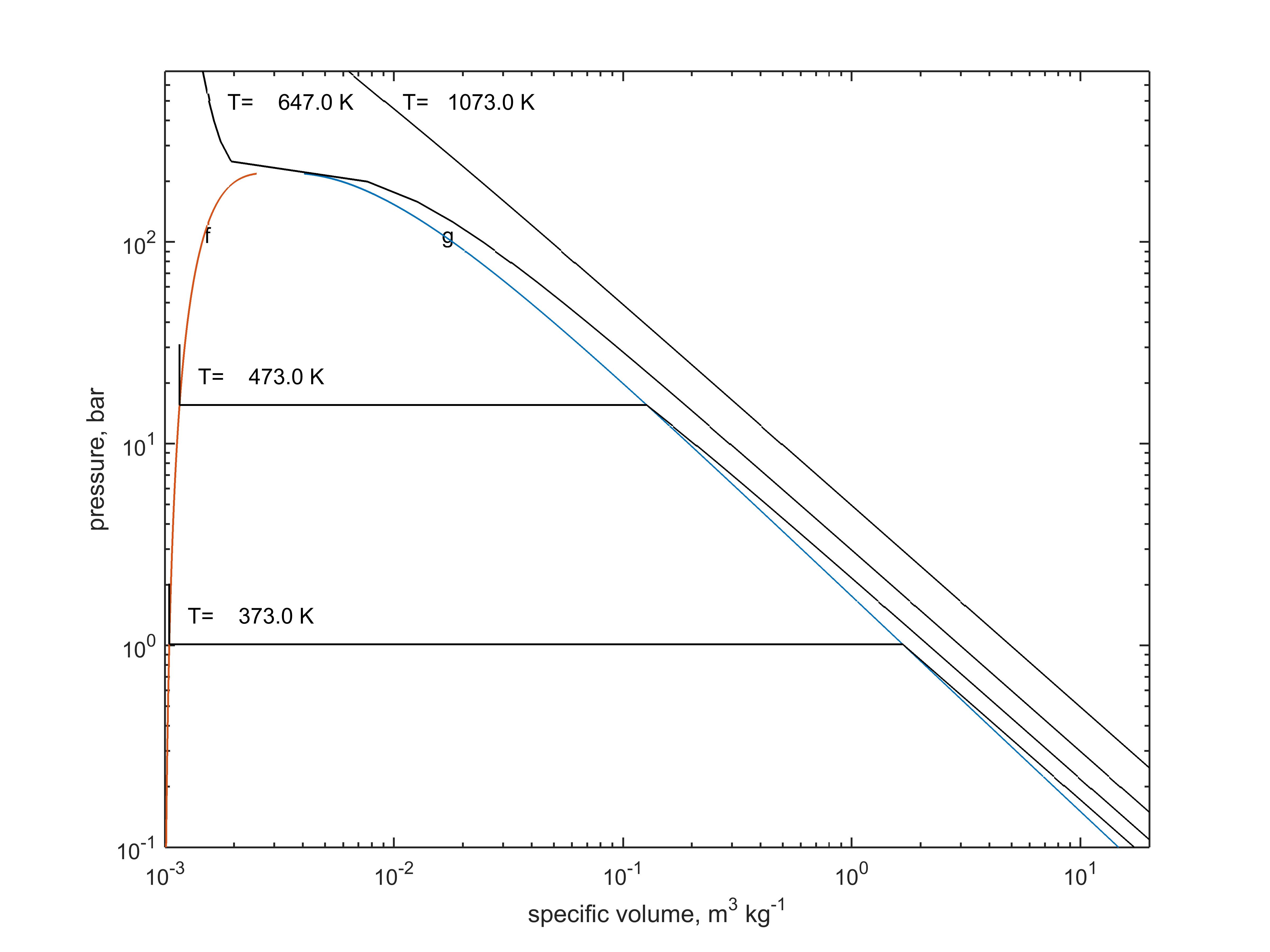
Figure 4 Pressure-volume (pV) diagram for water. Isotherms (curves for constant temperature) apply at the indicated temperatures. The red curve for saturated liquid is labelled 'f', whereas the blue curve for saturated vapour is labelled 'g'. Note that a log-log scale is used.
The phase diagram tells us where the vapour-liquid equilibrium is but offers no indication of the relative quantities of vapour and liquid. The above pressure-volume plot does offer such an indication. One notes (1) a red curve for saturated liquid (f) on which an infinitesimally small mass of vapour is in thermodynamic equilibrium with liquid (2) a blue curve for saturated vapour, on which an infinitesimally small mass of liquid is in thermodynamic equilibrium with the vapour (3) an isotherm (curve indicating constant temperature) at the higher temperature (1073K), similar in behaviour to that for an ideal gas (4) an isotherm at the intermediate temperature (647K), exhibiting an inflection point (5) two isotherms at the lower temperatures (473K or 373K), in part crossing from saturated liquid (f) to saturated vapour (g).
The International Association for the Properties of Water and Steam has published its calculations of the thermodynamic properties of steam. These are available in the MATLAB language in file XSTEAM.m, available from MATLAB central . Several calculators are available online. Properties have long be available as tables;
tables that preceeded IAWPS 1997 - perfectly adequate for teaching and learning - were prepared by Rogers and Mayhew.
(G. F. C. Rogers and Y. R. Mayhew, Thermodynamic and Transport Properties of Fluids, 5th Edition, published by
Wiley.) Sample values are shown in Table 2 . More recent data are tabulated by
NIST .
Online property calculators are available from
Zittau/Georlitz University of Applied Sciences and
Spirax Sarco .
Mayhew (reference needed) criticised calculators for not displaying the point of interest in relation to phase boundaries; to remedy this issue in part I provide my own
interactive chart .
Inside the bell shape formed by the f-g curves on Figure 4, steam is termed wet steam . It is a mixture of vapour and liquid (the two are considered as being at equilibrium). The dryness fraction (or quality), x, is the ratio of mass of vapour to total mass.
\begin{equation}
x = \frac{vapour \; mass}{vapour \; mass \; + \; liquid \; mass}
\end{equation}
Thus for a given pressure one can find saturation temperature, specific volume, specific enthalpy and specific entropy. Or we could use temperature as the independent variable. With wet steam the property of interest is computed from the saturation properties. I shall term the following the wet property equations.
\begin{equation} v = (1-x) v_f + x v_g \end{equation}
$$ s = (1-x) s_f + x s_g $$
$$ h = (1-x) h_f + x h_g $$
With regards to specific volume of liquid water, the very low value is frequently neglected (or an estimate of \(v_f \approx 0.001 kg m^{-3}\) suffices for many engineering calculations).
When dealing with saturated values (f or g) one cannot reasonably expect the specified independent variable (usually T or p) to match always a value in the tables.
Linear interpolation is often used.
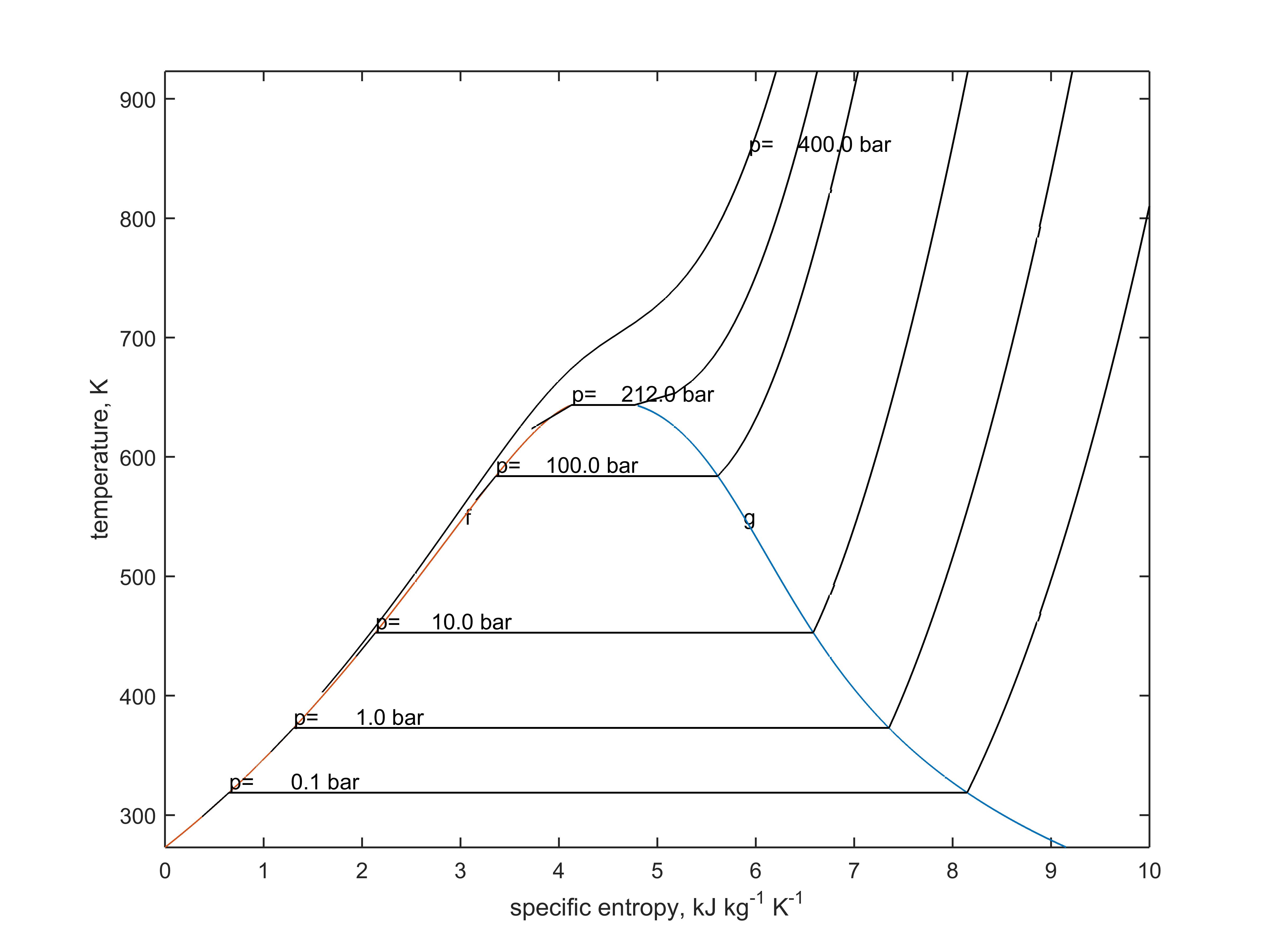
In addition to pV diagrams, the Ts diagram is popular in textbooks. In concept, the f-g envelope is not completely dissimilar. Whereas the pV diagram often features isotherms the Ts diagram often features isobars - curves of constant pressure. These are useful because boilers and condensers operate almost isobarically.
Figure 5 Temperature-entropy (Ts) diagram for water. Isobars (curves for constant pressure) apply at the indicated pressures. The red curve for saturated liquid is labelled 'f', whereas the blue curve for saturated vapour is labelled 'g'.
I provide an interactive steam T-s diagram as part of the current website . Use this for pedagogical purposes only, and not for commercial work. (Any student work submitted for assessment should use property charts or tables recommended by instructors.)
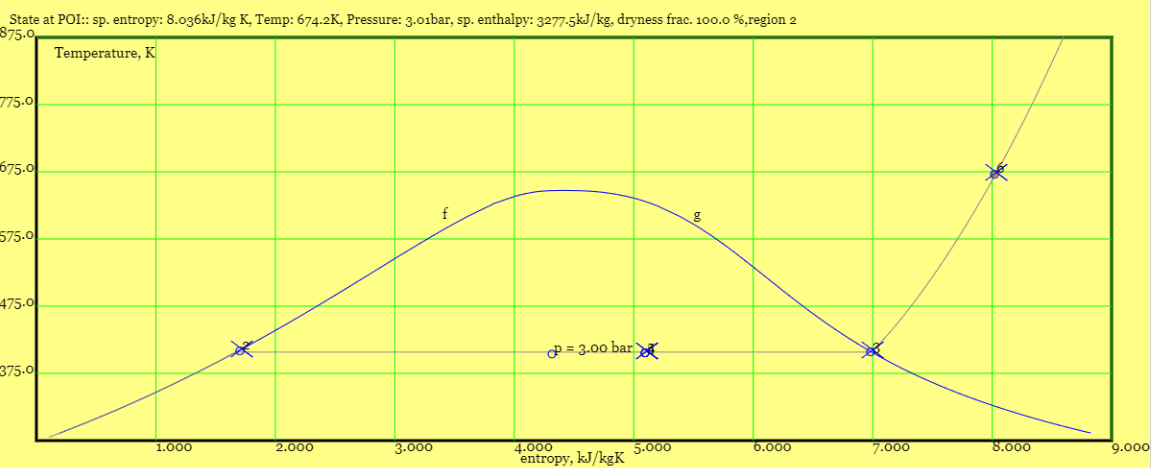
Example 2.070. For water/ steam held at a pressure of 3bar, find (1) the saturation temperature (2) the specific enthalpy of the saturated liquid, (3) the specific enthalpy of the saturated vapour (4) the specific enthalpy of wet steam with dryness faction of 65% (5) the enthalpy of superheated steam at 400 deg C (5) the specific enthalpy of sub-cooled liquid at 100 deg C.
For 1kg of fluid at constant pressure of 3bar, what heat input is required to change the condition from saturated liquid. Repeat your estimates for a pressure of 6 bar.
From the interactive chart.
A screen shot from the
interactive chart
is shown below with symbols corresponding to the points in question.
One moves the cursor to each point and left clicks. The table above the chart shows approximate values (subject to plotting accuracy). To get the specified dryness (65%) and temperature (673 K) some trial and error is required.
I used Thermodynamic and Transport Properties of Fluids, SI Units arranged by G.F.C. Rogers and Y.R. Mayhew, 4th Ed, Published by Basil Blackwell, London, UK
Result 1 was available on page 2, results 2-4 on page 4 and result 5 on page 6. The second worse error was \(7 kJ/kg\) and in the third significant figure, the worst was \(21 kJ/kg\) and in the second significant figure, and concerned saturated liquid. Again, the interactive chart should be used of approximate numbers only - either as a quick first estimate or a check of more time consuming calculations.
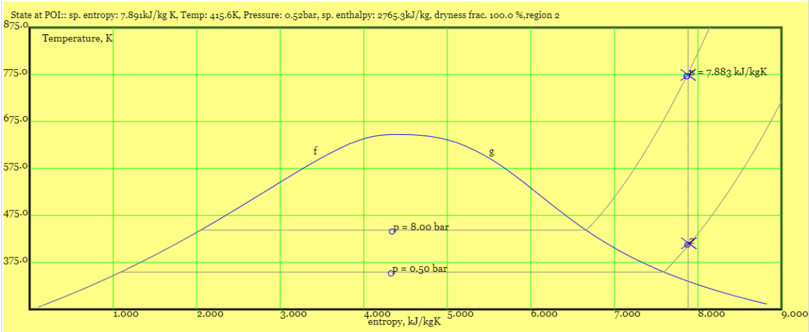
Example 2.080.
Superheated steam at 8 bar, 500 deg C undergoes an isentropic (constant entropy) process, such that the pressure is reduced to 0.5 bar. Plot this using the
interactive chart .
From the plot estimate the specific enthalpy of steam at the start and end end states.
From the interactive chart.
A screenshot
is shown below with symbols corresponding to the points in question.
I get \(h_1 = 3484 kJ/kg\), \(h_2=2757 kJ/kg\), constant \(s=7.891 kJ/kgK\).
From steam tables.
At 8 bar, 500 deg C I get \(h_1=3481 kJ/kg \) and \(s_1=7.866 kJ/kgK\). By
linear interpolation of (s,h) data pairs for \(p=0.5 bar \), I find at \(s= 7.866 kJ/kg/K\),
$$ h_2 = 2683 +(2780-2683) \times \frac{7.866-7.694}{7.940-7.694}=2751 kJ/kg $$
9.) Refrigerants
The intellectual skills employed in tackling steam power plant can easily be transferred to refrigeration.
The IAWPS algorithms have been adapted for some refrigerants such as ammonia and carbon dioxide. Although most undergraduate textbooks set problems relating to pure refrigerants, manufacturers have in recent years filled equipment with refrigerant blends. This is in order to maintain satisfactory operating pressures and mitigate environmental impact. (See, for example
see the EPA list of blends .)